LS7 Z06 ARE LS7-LS9 Retro Fit
Installation Instructions
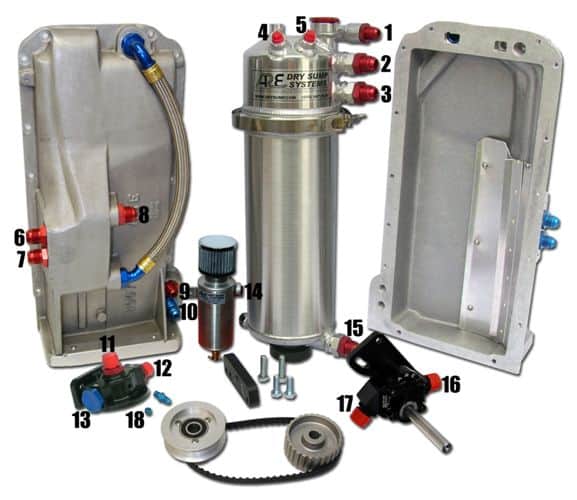
Dry Sump System (Stage lll Shown)
ARE Stage 3 Plumbing
For Stage System Eliminate #3, 16, 17 & 8
“PATENTED” MADE IN USA
Connections/Oil Lines as Numbered
1-14 Low Pressure Tank to Catch Can
6-2 -12AN (No. 044) Scavenge Return line from forward side of
sump pan (6) to tank upper inlet (2)
16-3 -12AN (No. 043) Scavenge line from outlet of new scavenge pump (16) to #2 tank inlet (3)
4 & 5 Low pressure (rubber) to Air Bridge (but may decide not to use depending on emissions. Also Spintric® air inlet to tank.
15-7 -12AN (No. 042) Supply line from bottom of oil tank (15) to rearward inlet (7) on sump pan. (Supplies Pressure Pump)
8-17 -12AN (No. 045) Sump pan scavenge outlet (8) to new scavenge pump inlet (17). Note: This line may change in the future to -16AN
9-12 -10AN (No. 046) line from sump outlet (9) to remote filter inlet (12)
13 Plugged. Alternative inlet depending on location of filter
18 Plugged or use as an auxiliary outlet for mechanical oil pressure gauge
NOTE: REMOVE FACTORY WINDAGE TRAY BEFORE INSTALLING ARE DRY SUMP PAN
NOTE: LINE NUMBERS ABOVE REFER TO KATECH PRE-MADE LINES AVAILABLE DIRECTLY FROM KATECH- CONTACT JASON@ (586) 791-4120
Above directions are for oil cooler installed in pressure side of system. This is the preferred way to cool the LS-7 System providing the factory pressure pump maintains adequate oil pressure. Loss of pressure can sometimes occur due to extra distance & flows of oil through cooler. The oil cooler may also be installed in scavenge return lines to tank. ie: 7-2 or 16-3 (stage III)
First oil Filling
The System will hold between 9 and 12 quarts (existing holds 8 quarts)
1. Do NOT add oil to the tank at time of installation of the pan (as oil will flow into the pan)
2. Through the red cap on the oil tank, pour say 8 quarts of oil, Add 2 quarts to Engine
3. Crank the engine (plugs removed) to build up oil pressure
4. Replace the plugs
5. Start the engine and allow to warm to operating temperature
6. Oil Pressure should stabilize around 50 PSI or more
7. After checking pressure, leaks etc, turn off engine and immediately open the red cap and check the oil level
8. Add oil until the oil level is just AT (NOT ABOVE) the level of the internal deaerater. (Slots)
NOTE: It is very important that when checking tank oil level (#8 above) that the engine has been run above idle, and shut off when level in tank checked not more than 5 minutes after shutting engine off #7, #8 above.